Trajectory control study faces 2 types of
issues:
1. Assuming - as a first step for sake of simplicity - that the game is ideally continuous,
one issue relates to the
game-engine imposing its
own dynamics for velocity.
Commands issued by a bot/player are not instantaneously reflected in the actual variables ouput by the game-engine.
Firstly, elementary trajectories ( lines, circles,...) that composes a full path
typically last several seconds, whereas game-engine response times are around several hundredth of seconds, ie
the game engine will introduce a
transient "perturbation" on trajectory changes.
Secondly, some trajectories ( typically the circle) implies steady variables changes ( ie yaw with constant rotation speed for a circle),
which, depending on the game-engine, may generate a
constant error between the
command ( yaw in our example) and the game-engine output ( see
C1LL filter response curve to a ramp input viewed as a constant yaw variation).
2. A second issue is related to the game being actually numerical, which introduces supplementary problems related to
sampling-holding
and the choice made for an
integration scheme in the game-engine.
Hence, the trajectory control study is loosely following an approach
excluding game-engine dynamics, then testing with a continuous game engine, then testing with a numerical model reflecting as closely as possible the game-engine behaviour.
Game-engine for testing will be here based on 2 types:
- one, the "BaseEngine", where velocity modulus and velocity angle are controlled
through 2 different channels ( like a simplified model of an airplane)
- one modelling
the Half-life engine,
where velocity modulus and velocity direction are strongly coupled (in the engine) during turns,
the Base engine pseudo-code
Note: no backwards move.
// feedbacks:
vVel,
Yaw,
M ; commands:
UE_yaw,
UE_mVel
// for tests:
Ek_Yaw= 1-exp(- kYaw*
T) with kYaw= constant ( =4 in tests) or
Ek_Yaw=1;
// for tests:
Ek_mVel= 1-exp(- kmVel*
T) with kmVel= constant or
Ek_Yaw=1;
mVel= sqrt( dotproduct(
vVel,
vVel));
//velocity direction control
DeltaYaw= wrap180(
UE_yaw-
Yaw);/*in [-180, 180[*/
YawRate=
Ek_Yaw* DeltaYaw/
T; /*0 <
Ek_Yaw < 1*/
YawRateMax= YAWRATEMAX;
if(
mVel!=0) YawRateMax= (YAWRATEMAX, ACCTRANSMAX/
mVel);
YawRate= min( max(YawRate, -YawRateMax), YawRateMax);
Yaw= wrap360(
Yaw+
T* YawRate);//update
//velocity modulus control
AccL=
Ek_mVel* (
UE_mVel-
mVel)/
T;/* 0 <
Ek_mVel < 1*/
AccL= min(max( AccL, DECELLONGMAX), ACCLONGMAX);/*DECELLONGMAX< 0*/
mVel=
mVel+
T* AccL;//update
//updating position
Mx=
Mx+
T*
mVel* cos(
Yaw);
My=
My+
T*
mVel* sin(
Yaw);
Moving towards a destination point
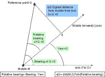 Principle: Whatever the current mobile position,its velocity vector points towards the destination point.
In its simplest form: UE_vVel= vMS/ T, which, game engine dynamics let aside,
would instantaneously place the mobile on the destination.
Decomposing into modulus and angle, and using a more general formulation
UE_mVel= k_D* MQ;/* with 0 < k_D ≤ 1/T*/
UE_mVel= min( UE_mVel, SPEEDBOUND);/* SPEEDBOUND being a botAI velocity bound*/
Bear= (aBearMQ= )vectorToAngle360( vMS);
UE_yaw= Bear;
This control law is the basis for the widespread bot "waypoint navigation"
, ie the "Navigation towards points" system.
Actually , the last equation is a particular case of a the following control law
, where the relative bearing U_VelRBear is controlled through UE_yaw: UE_yaw= Bear- U_VelRBear, where U_VelRBear is zero.
Setting different formulas for U_VelRBear results in different trajectories,
but the really interesting variation is addressed below in "Moving passed and around a point".
In all cases, numerical simulation will generate undesirable jittery velocity direction
changes when the mobile is on or very close to the destination point ( bot dancing around its center point), which calls for specifc adjustments.
Whatever the navigation system, this trajectory control process will always be used at least on the last path segment leading to the final destination whenever it is a point or a circular area.
Moving passed & around a point
Principle: assuming U_Dist<<
MQ, the bot moves along a straight line maintaining a
constant distance U_Dist to
Q, ie the trajectory is tangential to the circle of
radius U_Dist and center=
Q, until
vVel is perpendicular to
vMS; the trajectory becomes then circular.
UE_yaw=
Bear-
U_VelRBear, with
U_VelRBear=
Sgn *
asin( min( U_Dist/
MQ, 1)).
Sgn defines on which side of the trajectory
Q will lie.
This control law is the basis for the "Navigation around points" system,
where U_Dist > bounding radius of the bot .
Note: Setting U_Dist= 0 gives "Moving towards a destination point".
With the BaseEngine
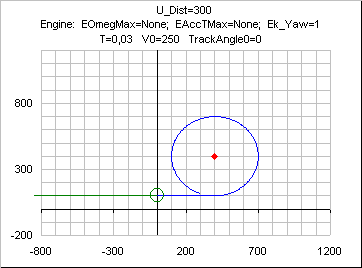
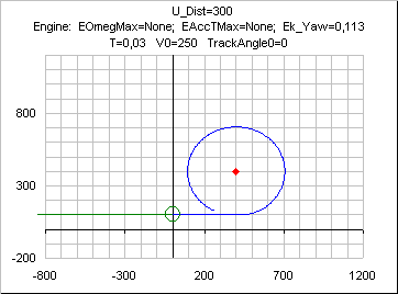
In some cases some variables( like when
Ek_Yaw=1) will flip-flop around a constant value on the circular portion of the curve: this is not a numerical problem, it just results from the computation of
UE_yaw, keeping the trajectory tangential to the circle at all times; the effect can be best seen on the following curve , where
T has been set to a high value ( ie high
T*
mVel/ U_Dist) .The curve also shows that the trajectory remains ouside the circle.
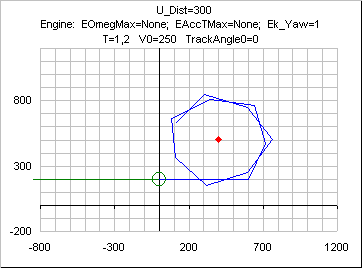
Besides, the actual radius is greater than U_Dist for
Ek_Yaw decreasing; the error being irrelevant for my own applications in a "Navigation around points" system, I did not look for adjustements or more complicated designs ( like PID).
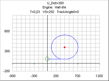
With the Half-life engine
The following curve does not change noticeably for
T in max allowed range ( < 0.25 seconds).
Rallying & moving along a directed line
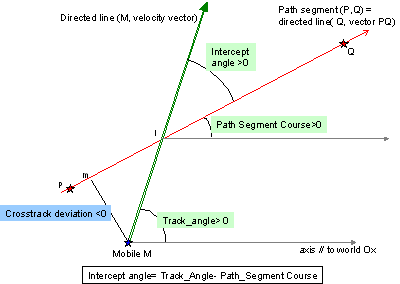 Principle
: Whatever the mobile current position, it moves towards the line,
and when on it, it moves along the line in the right direction.
Assuming the directed line is defined by 2 points P and Q, and
Course being the corresponding direction angle:
the crosstrack deviation is
XTD= projection of
vQM on the +90 degree-normal to the vector
vPQ
= z component of crossproduct(
uvPQ,
vQM), where
uvPQ is a unitary vector;
XTDVel= projection of velocity on the +90 degree-normal to
vPQ= z component of crossproduct(
uvPQ,
vVel)=
mVel* sin(
IcptAng)=
mVel* sin(
aVel-
Course)
For sake of simplicity, it is assumed in this paragraph that the directed line is the world RefFrame x_axis.
The mobile should then reach a steady state where y=
XTD=
XTDVel= 0, and
aVel=
Course.
A simple approach gives a proportional control law as
U_XTDVel= -
k_Y*
XTD.
With a game engine bound on speed, this would result in a straight move perpendicular to the line until
XTD=0.
One could bound
U_XTDVel to a max value lower than max speed, but
variation of
mVel actually distorts the resulting trajectory in an unnatural way.
As
XTDVel=
mVel* sin(
IcptAng), and
aVel=
IcptAng+
Course is controlled through
UE_yaw,
a better control law could be
U_IcptAng= K_RadToDeg* asin( min(max(-
k_Y *
XTD/
mVel, -1),1));
UE_yaw=
Course+
U_IcptAng;
Getting rid of the asin ( safe as asin(x)/x is monotonous, ≥ 1 and close to 1 where x is close to zero)
, and allowing the intercept angle to be bounded to any choosen value instead of 90 degrees only,
a final control law that works is:
U_IcptAng= min(max( -K_RadToDeg*
k_Y*
XTD/
mVel; -INTERCEPTANGLEMAX), INTERCEPTANGLEMAX)) where 0 < INTERCEPTANGLEMAX ≤ 90
( in practice: 45 ≤ INTERCEPTANGLEMAX ≤ 90 ).
The constant value of k_Y depends on the game engine responsiveness to a UE_yaw input
and the acceptable (damped ) oscillations.
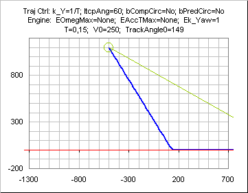
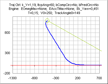
With the BaseEngine
if Ek_Yaw=1 ( no lag on yaw) and k_Y= k_Ymax= 1/T, the resulting trajectory is basically a straight line intercepting the directed line under an angle of +-INTERCEPTANGLEMAX.
if Ek_Yaw=1 ( no lag on yaw) and k_Y< 1/T, , the straight line is followed by a close-to-exponentially decaying y with velocity direction getting close to the line direction.
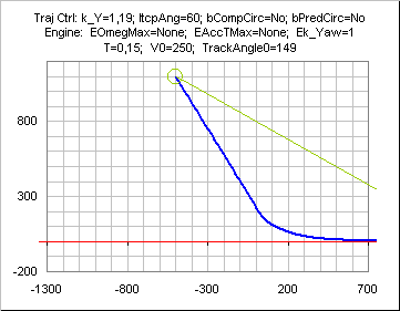
if Ek_Yaw<1 ( and k_Y tuned accordingly for stability), the straight line is preceded by a turn due to the engine lag.
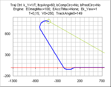
Bounds on yaw speed( or radius or mAccT)
If yaw speed is bounded, the initial phase is a turn towards INTERCEPTANGLEMAX direction.
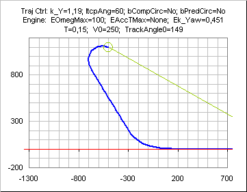
The sign of this initial turn depends on the sign of (initial
RBear - (180±INTERCEPTANGLEMAX)).
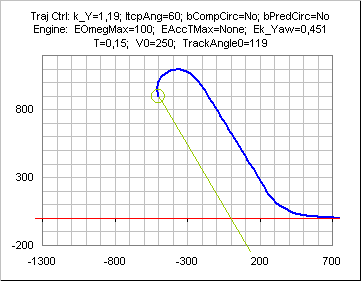
It is possible to tune the limit angle independently from INTERCEPTANGLEMAX.
Besides, the control law might initiate the final rally phase too late
and generate an overshoot, ie the trajectory markedly crosses the
directed line at interception time. This will always occur as seen above if
Ek_Yaw=1 ( no lag on yaw) and
k_Y= k_Ymax= 1/
T.
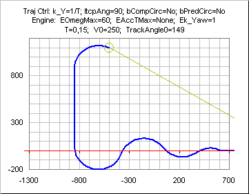
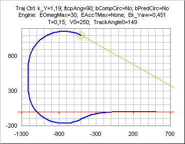
A way to prevent that while maintaining a constant speed modulus is to
introduce a second bound IcptMax_Engine on
U_VelRBear corresponding
to a circular trajectory tangential to the directed line, and taking
the min of this bound and INTERCEPTANGLEMAX:
RadiusMin_Omega= K_RadToDeg*
mVel/ ENGINE_OMEGAMAX;/*OMEGAMAX= max yaw speed in deg/s*/
RadiusMin_AccT=
mVel*
mVel/ ENGINE_ACCTMAX;
RadiusMin= max( RadiusMin_Omega, RadiusMin_AccT);
xa= 1- abs(
XTD)/RadiusMin;
xa= min(max(x,-1),+1);
IcptMax_Engine= K_RadToDeg* acos( xa);
InterceptAngleMax= min( INTERCEPTANGLEMAX, IcptMax_Engine);
Using this adjustment process, velocity increases during the last circular turn might nevertheless generate overshoots.
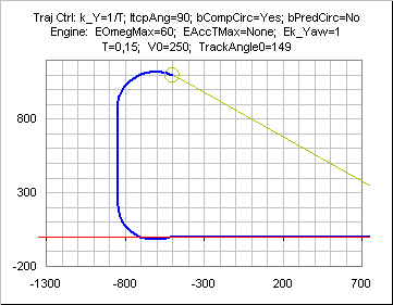
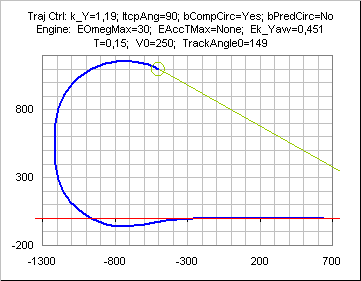
A further improvement is to use a prediction on
XTD instead of
XTD to compute IcptMax_Engine:
XTDPred=
XTD+ (
T/
Ek_Yaw)*
vVely;
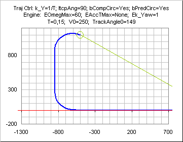
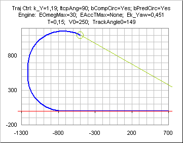
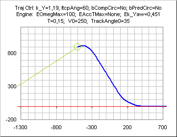
The trajectory is rather impervious to velocity changes, as evidenced on the following curve ( change on velocity command from 250 to 80 during the final turn), except may be in some cases of increasing velocity as mentioned here above.
 With the Half-life engine
k_Y
 should depend on Timestep, but
k_Y= sv_friction/4 is a low conservative value, and twice that value is OK.
The initial turn cannot be seen due to the figure scale, because it is actually very fast.
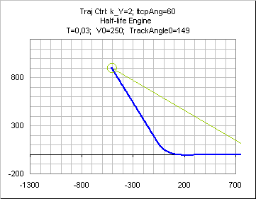
The section
turns provides
the necessary information to code overshoot avoidance, but it does not seem useful and the implementation corresponding to the following curve does not include anything mentionned in the preceding Base engine paragraph.
Reaching a point in a given direction
x, y,
vVely,
vVelx are measured in a local frame having the destination point for origin, and having its x-axis along the given direction ( ie
Course= 0);
UE_yaw and
Bearing are also measured in this local frame.
The Bearing is the bearing to the destination point:
Bearing= atan2(y,x) in [0, 360[.
LINE: The first easy solution is to move straight to the destination, then change yaw to the given direction:ie
UE_yaw=
Bearing then
UE_yaw= 0 when on dest;
or
vVely/
vVelx= y/x then
UE_yaw= 0 when on dest;
This works if a stop on the destination is possible or turns are instantaneous, which is barely the case.
CIRCLE tangential to x-axis for x=y=0:
UE_yaw= 2*
Bearing;
or
vVely/
vVelx= 2*x*y/( x*x-y*y);
or
vVely/
mVel= 2*x*y/(d*d); d= sqrt( x*x+y*y)
The radius is implicitely determined by the initial values of x and y not null as Rad= -( x*x+y*y)/(2*y);
PARABOLA tangential to x-axis for x=y=0:
UE_yaw= atan(2* tan(
Bearing));
or
vVely/
vVelx= 2* y/x;
Actually , the 3 hereabove curves are members of more general families
F1: CONICS FAMILY: ( insures
vVely=0 on x=y=0)
vVely/
vVelx= 2*y*(x+ B*y)/( x*x-(c*y*c*y));B> c: hyperbolas, B= c: parabolas, B< c: ellipses.
More families I could think of are
F2:
UE_yaw= K* Bearing;/*K= 1 for the line, K=2 for the circle*/
F3:
vVely/
vVelx= K*x*y/( x*x-y*y);/*K=2 for the circle*/
F4:
vVely/
mVel= K*x*y/(d*d);/*K=2 for the circle*/
F5:
UE_yaw= atan(K* tan(
Bearing)) or
vVely/
vVelx= K* y/x;/*K= 1 for the line, K=2 for the parabola*/
I only tested F2 family, which is absolutely great (with some adaptation, especially for K > 2) to insure smooth turns in various initial conditions.TODO: figures wont hurt
Except for the F1 family thanks to more parameters, the velocity angles are set by the equations, ie they can be quite different from the bot current ones when initiating the curve.
A key point to check when choosing/testing a family is that
vVely=0 on x=y=0.
Decelerating & stopping
As one would expect, with a game engine as Half-life engine, setting the wished velocity
to zero (
UE_mVel=0) does not result in actual velocity being instantaneously zero.
Reaching the final destination point ( ie
MQ=0) at null speed can be achieved 2 ways:
1. by a control law on distance, which is the best solution if available:
UE_mVel=
k_D*
MQ/
T works with an engine such as the base engine without bound on decceleration;
it does not in the other case, and not quite with Half_life engine.
2. by open-loop prediction: find a function returning the distance run until full stop from a given velocity when a zero velocity is commanded; trigger a null velocity command
UE_mVel=0 when
MQ becomes equal or less than the distance returned for the current actual velocity.
This cannot result in a final
MQ exactly equal to zero; requiring a high precision
positioning, ie a small waypoint radius, with such a solution is asking for trouble.
see
Stopping Distance for Half-life.

 Principle: Whatever the current mobile position,its velocity vector points towards the destination point.


 Principle: Whatever the mobile current position, it moves towards the line,
and when on it, it moves along the line in the right direction.


